Toolkits menu: 
Start the ROI Toolkit from the Toolkits menu: 
The ROI Toolkit frame will now appear.
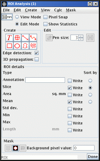
There are eight types of ROI, which can be created by clicking on the icon in the ROI Toolkit frame:
 Text
Text
 Marker
 Line
Line
 Curved line
 Rectangular
 Elliptical
 Irregular, manually drawn
 Irregular, contour following
For handy ROI creation you can also bring up the "handy ROI tools"
window from the ROI Toolkit: 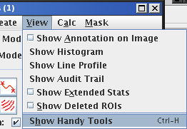 .
.
This pops up the window show below:

There are different ways to create and edit the different types of
ROI. These are detailed below.
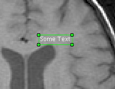
To create some text annotation, ensure that you have a slice selected, then
click on the
The status bar given you the instructions "click on the selected slice
and type text;
All text ROIs are displayed with text in the same font size, and with the
same font colour. However, the size and colour are configurable using the
ROI Toolkit Preferences.
Note: you also rapidly create some text by pointing with the
mouse within the selected slice, and pressing the 't' key on
your keyboard.
To create a marker, ensure that you have a slice selected, then
click on the
The status bar given you the instructions "click on the selected
slice; Esc to cancel". To drop a marker, click on your chosen
point somewhere in the selected slice. To cancel the operation,
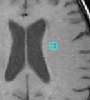
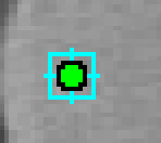
press the "Escape" key on the keyboard. The marker will look
like this:
Note: you also rapidly create a Marker by pointing with the
mouse within the selected slice, and pressing the 'm' key on
your keyboard.
The status bar given you the instructions "click, hold and drag
to define; Esc to cancel". To define a line, click
point somewhere in the selected slice and hold the mouse button
down; this will be the first end of the line. Drag the mouse to
the other end of the line, and release the mouse button. The
line will now have been defined. To cancel the operation,
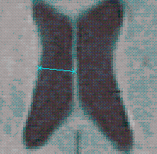
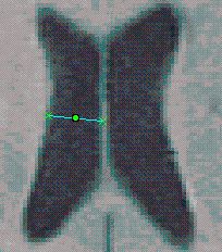
press the "Escape" key on the keyboard. The line ROI will look
like this:
To create a curved line distance measurement, ensure that you have a
slice selected, then
click on the
The status bar given you the instructions "click or trace points
around the shape; Esc to cancel". To define a curved line,
you can click the mouse at individual points around the curve,
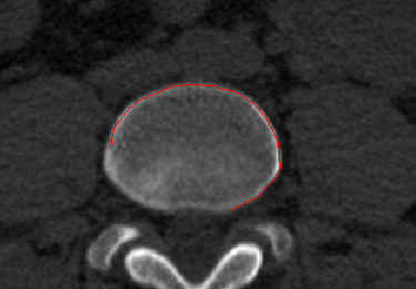
or you can hold the mouse button down to draw the curve. As the ROI is
being drawn, it appears as a red outline:
To end the curve, double click with the
mouse. To cancel the operation press the "Escape" key on your
keyboard.
Note: you can zoom and scroll the image as you are drawing the
outline, as usual.
To change the curved line, click on it, after which it will
then appear with nine "handles", as shown below:
To create a rectangular ROI, ensure that you have a slice selected, then
click on the
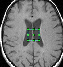
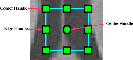
This will create a "default" rectangular ROI in the middle of the
selected slice:
To create a elliptical ROI, ensure that you have a slice selected, then
click on the
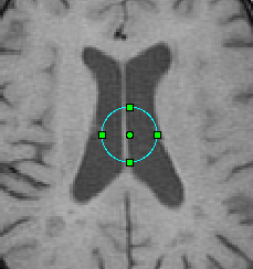
This will create a "default" elliptical ROI in the middle of the
selected slice:
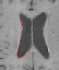
Irregular ROIs are drawn manually on the selected slice.
Click on the
You can click the mouse at individual points around the outline of the
feature you want to measure, or you can hold the mouse button
down to draw around the outline. As the ROI is
being drawn, it appears as a red outline:
To close the outline, and create a completed ROI, double click with the
mouse. To cancel the operation press the "Escape" key on your
keyboard.
Note: you can zoom and scroll the image as you are drawing the
outline, as usual.
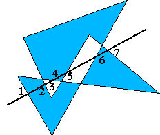
Note: for ROIs drawn by hand that have segments of the outline
that cross, the "even-odd winding rule" is used to define the
interior and exterior portions of the ROI. The figure below
shows such a shape:
To enable or disable edge detection click on the Edge Detection check
box:
Uncheck the Edge Detection check
box, then click on the
To cancel the operation press the "Escape" key on your keyboard.
Ensure that the Edge Detection check box is ticked,
then click on the
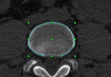
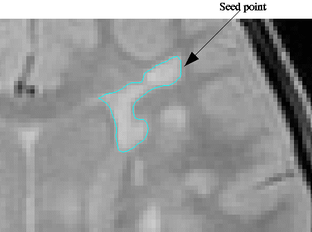
Jim will now have produced a contour, shown in light
blue, outlining an image feature. Below is the result of
applying edge detection and contouring to the edge of brain
lesion. The algorithm used to find an edge is explained in the
algorithms section.
Normally, contoured ROIs are only created in the slice in which
you click the mouse. However, if you select the
Turning pixel snap on (by checking the Pixel Snap check box
The ROIs Toolkit can be set so that the vertices of some ROIs (Line, Curved Line and
Irregular ROIs) can snap either to the corners or to the centres of
pixels. Change between snapping to centres/corners, by setting your
preference in the ROI
Preferences dialog.
ROIs created by contouring are unaffected by Pixel Snap.
Text Annotation
[Keyboard accelerator:
point to a selected image slice and press the 't' key.]
 icon.
icon.
Markers
[Keyboard accelerator:
point to a selected image slice and press the 'm' key.]
 icon.
icon.
Lines
To create a straight line distance measurement, ensure that you have a
slice selected, then
click on the  icon.
icon.
Curved Lines
 icon.
icon.
Rectangular ROIs
 icon.
icon.
Elliptical ROIs
 icon.
icon.
Irregular ROIs
 icon to
start drawing: the status bar gives the instructions: "click or
trace points around the outline; Esc to cancel".
Contoured ROIs
[Keyboard accelerator:
point to the edge of a feature and press the 'c' key.]
A contoured ROI follows a contour, or level of intensity, from a point
where the mouse is clicked. Optionally, edge detection can be
turned on, so that the contouring function automatically finds the
edges of image features in the vicinity of the mouse click, and
then follows the outline of that feature.

Contouring without edge detection
 icon.
The status bar gives the instructions: "click on the selected
slice at the contour start point; Esc to cancel". Click on the
selected slice at the position where you want the contour to
start. The algorithm used to find the contour level is explained in the
algorithms
section.
Contouring with edge detection
 icon.
The status bar gives the instructions: "click on an edge the selected
slice; Esc to cancel". Click on the
selected slice at the edge of an image feature.
To cancel the operation press the "Escape" key on your keyboard.
Propagation in 3D
 check box, then the
contour level and initial contour location are propagated to
adjacent slices. If a contour at the same contour level are found
close to the same location, then a contour will also be created in
these slices. The search for the contour level take place in a
5×5 square region of pixels, searching in an outward spiral
centred at the contour location. If the contour level is not
found within the search area, then propagation stops; otherwise an ROI is
created in the adjacent slice, and propagation continues to the
next adjacent slice.
Pixel Snap
![]() ) causes the outlines of ROIs to snap onto
the nearest corners or centres of image pixels. Thus, for example with Pixel Snap
turned on, Rectangular ROIs will always contain a whole number
of pixels. Without Pixel Snap, ROIs are free to have any shape
defined by the user.
) causes the outlines of ROIs to snap onto
the nearest corners or centres of image pixels. Thus, for example with Pixel Snap
turned on, Rectangular ROIs will always contain a whole number
of pixels. Without Pixel Snap, ROIs are free to have any shape
defined by the user.