Statistics
This section details the computation of ROI
statistics by the ROI Toolkit. The ROI Toolkit provides a
high-precision estimate of the following ROI statistics:
Line and CurvedLine ROIs have an additional statistic:
If extended statistics are shown, then the following statistics are computed:
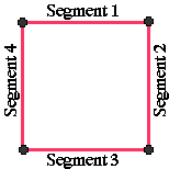
For ROIs that enclose an area, each ROI is defined by the (closed path) outline that encloses the region. For example, in the case of a Rectangular ROI, the outline consists of four line segments joining the four corner points:

Elliptical ROIs present a particular problem, since calculation of intensity statistics with a truly curved outline would be problematic and very slow. Calculation of intensity statistics for Elliptical ROIs is therefore done by representing the outline by a series of straight line segments. If the outline is represented by n straight line segments, then the error between the true area of the ellipse and the approximated area is:
(π - (n * sin(π/n) × cos(π/n))) × 100% / π
In Jim versions up to 4.0 n is set to 360 (i.e., for a circular ellipse, each line segment subtends an angle of 1° at the centre), which leads to a difference of 0.005% between the true ellipse area and the area of the ellipse represented by straight line segments. Computation of intensity statistics for ROIs involves multiplying pixel intensities by the the area of pixels that lie with the outline of the ROI. Given a random distribution of pixel intensities with an Elliptical ROI, we therefore expect an error of the order of 0.005% for intensity statistics.Note: the area statistic returned for an Elliptical ROI is always the true area of the ellipse (= π × semi-major-axis × semi-minor-axis).
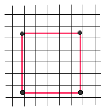
The vertices of an ROI outline may be positioned anywhere with respect to the array of image pixels, so the same Rectangular ROI shown above superimposed on the pixel array may appear like this:

Σ( ai × Ii) / A.
For a Text or Marker ROI, the mean pixel intensity is the intensity of the pixel at the centre of the text or beneath the marker. Let µ be the mean pixel intensity.square root((Σ(ai × Ii × Ii) - µ × µ × A) / A).
The exception to this is for Text and Marker ROIs, where the standard deviation in pixel intensity is always zero.The algorithm for Line ROIs is similar to that described above. However, Line ROIs do not enclose any area, and so in the description above substitute "length" for "area".
All shape intersections are performed using the standard Java
intersect methods in the java.lang.geom package.
Errors in area calculation have been tested for typical and
atypically-shaped ROI designed to elicit the largest
errors. Errors in the worst cases have been found to be within 1 part
in 1000, and for most practical ROIs, errors will be much better
than this. These errors are thought not to significantly
compromise the validity of results produced by Jim.
The following generalisations also apply:
Masking operations set the pixel intensity values in an image
according to whether pixels are inside or outside an ROI or set
of ROIs. If more than one ROI is to be used as a mask, then a
composite shape is first formed from the
The way that the intensity (level) of a contour is determined from a starting pixel
is described here. The starting pixel may have been derived
either from a mouse click in the case of without edge
detection, or by edge
detection as the pixel at the maximum gradient.
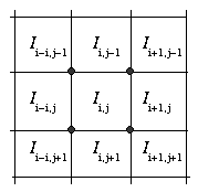
The starting pixel at location (i, j) is shown below, and has
intensity Ii, j.
Extended Statistics
Perimeter
An ROI's perimeter is defined as follows:
Feret's Diameters
A Feret's diameter is the separation between a pair of parallel
lines that just enclose the ROI, for a particular angle between
the parallel lines and (say) the x-axis. As the angle is
changed by sweeping through 180°, so the Feret's
diameter will change. The minimum and maximum separation of
the lines found over all angles are called the minimum and
maximum Feret's diameters.
Masking
union (see
the java.lang.geom package) of the individual ROIs.
Contour Intensity

| North West Corner Intensity | (Ii-1, j-1 + Ii, j-1 + Ii, j + Ii-1, j) / 4 |
|---|---|
| North East Corner Intensity | (Ii, j-1 + Ii+1, j-1 + Ii+1, j + Ii, j) / 4 |
| South East Corner Intensity | (Ii, j + Ii+1, j + Ii+1, j+1 + Ii, j+1) / 4 |
| South West Corner Intensity | (Ii-1, j + Ii, j + Ii, j+1 + Ii-1, j+1) / 4 |
The contour level is set to the average of the four corner intensities.
Edge detection can be used to create Irregular ROIs by
clicking at a point in the image near an edge. Edge detection
finds the strongest edge in the region of the mouse click, and
starts contouring from the pixel at the strongest edge
location. In Jim versions up to 4.0, the algorithm used to
find the edge is described below:
y = a + bx + cy.
exp(-(r/5)2),
Edge Detection
The constants in the edge detection algorithm (for the search area, kernel size, and
spatial weighting function) were determined by trial and
error to give good results when outlining brain lesions.