At the top of the Jim's 3-D display are the general controls that affect the objects that are loaded into the display.

The effect of each of these is described below.

Light levels can be set between 0 (light off) and 1 (brightest).
The directional light source is situated behind you (the viewer), but you can set the position of the light source (left-right, top-bottom) using the light direction gadget:

The white spot represents the light source. To change its position, click
within the black square to set the light source to that position. You can
also drag the light source with the mouse.
Move the sliders to change the position of the orthogonal planes:
Move the:
Click the cut out buttons to change which segment of the image is cutout
when you are displaying a surface, and the
Click the:
The effect of changing the cutout is shown below.
Click on the
Note: you cannot rely on Jim displaying images with the
correct spatial orientation. Xinapse Systems makes no guarantees about the
correctness of the orientation, and the view you see cannot be relied upon to
be true to the patient left-right/anterior-posterior or superior/inferior
orientations.
If you independently verify that the displayed orientation is incorrect,
you can make a manual correction by flipping any of the axes by selecting
the appropriate
Note: if you have more than one 3-D object displayed, with different
fields of view for each, the displayed bounding box will be large enough to
contain the all of the displayed objects.
The origin of the coordinate system is at the centre of the 3-D image pixel
matrix. The x-coordinate increases with increasing column number; the
y-coordinate increases with increasing row number; and the z-coordinate
increases with increasing slice number.

 check-box is selected:


Cutout X+ Y+ Z+
Cutout X+ Y- Z+

 button to flip the
z-coordinate so that the image is displayed with the correct orientation in
space.
You can suppress this message for the rest of your session using Jim
by selecting the
  check-box.
 check-box:
 check-box.

 check-box.

You can create screen shot pictures for inclusion into presentations, reports and Web pages. The screen shot image shows exactly what is shown in the 3-D image display window.
Compose the image in the display to appear as you want it, then
select "Screen shot ..." from the File menu:

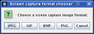
A dialog will pop up, allowing you to choose the format for the screen shot picture.

You will then be asked to select a folder and file name for the screen capture image.
You can rotate, zoom and scroll the view of the data using the computer mouse.
To reset the view of the data to a standard view, click the  button.
Using the left mouse button allows you to freely rotate the image to any
orientation. However, it is easy to become disorientation and hard to get
exactly the view you want. To make life easier, you can constrain the rotation
by selecting the  check-box. Then
select the axis about which you want to constrain the rotation (x- y- or
z-axis). Then, when you rotate the image, only certain types of rotation will
be allowed, keeping the selected axis constrained to a fixed plane in space.
If you want a particular, reproducible view position, you can set an exact
view location using by selecting Set view ... from the
View menu. This brings up the dialog below:

Using this, you can set:
By stepping through various angles, it is possible to create a series of screen shots, that when played in sequence, give an impression of motion around the 3-D displayed objects. The animated GIF movie below was created by making a series of GIF screen shots, before putting them together as an animated GIF. However, this process is rather tedious - please see the section on recording cines instead.
